
I2C Jumpers
NoteThe wire colors below may not reflect those in your kit. You are free to use what you want so long as you remember what each one is! There is no official standard.
Electrons have no concept of color and just do electron things.
If USB is plugged in at the moment, you’ll want to pull the cable to avoid shorting anything out.
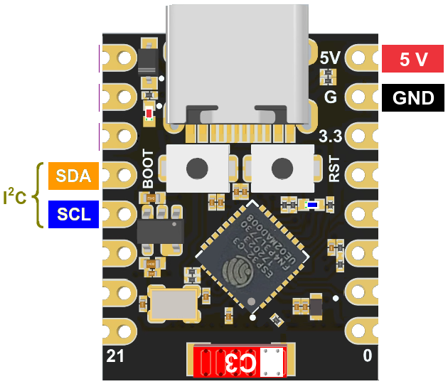
There are quite a number of pins on the ESP32 board, but only a few are important for our purposes. The I2C pins are on the left side below, right next to the boot button:
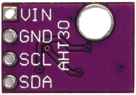
On the AHT30 board, they are opposite of the mounting hole on the board.
Note that they are backwards from the ESP32 pins:
With the opposite layout in mind, the pins can be connected on the breadboard with jumpers.
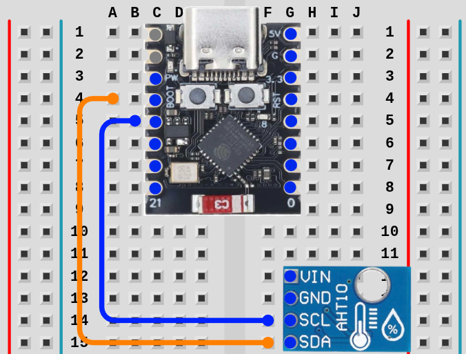
TipIt’s easier to start with SCL since the pins are closer together.
TipCounting pin holes is difficult to see without help for most people. If you lightly place the pin in the first hole at the top of the ESP32, you can gently pull the pin down the board, counting ridges between holes (2,3,4,5).
For the AHT30, place the pin over the bottom connection and lightly drag it up one hole.
Next Up: Power